Understanding Plant 3D Isometrics
What are Plant 3D Isometrics?
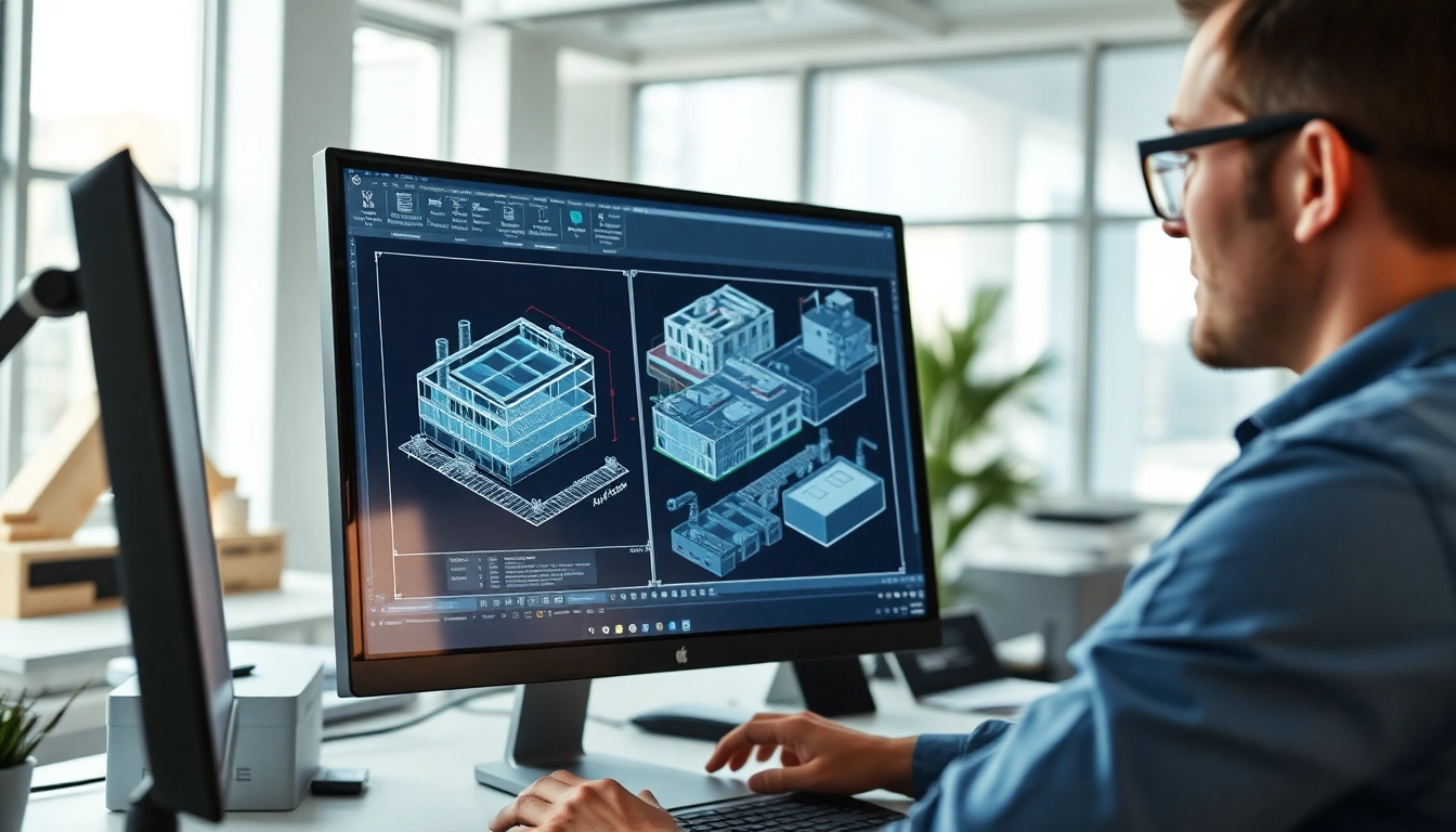
Plant 3D Isometrics are specialized technical drawings that represent piping systems in three-dimensional space, allowing for precise visualization and documentation of plant designs. They are crucial for the efficient planning, installation, and maintenance of various industrial systems, particularly in fields like oil & gas, water treatment, and chemical processing. In essence, these isometric drawings provide a 3D perspective while maintaining clarity in the 2D format traditionally used in engineering documentation.
Importance of Isometrics in Engineering
Isometric drawings serve a vital role in engineering projects as they encapsulate all necessary data, such as dimensions, materials, and assembly instructions. This clarity helps in significantly reducing errors during construction or retrofitting phases. Moreover, by detailing the layout and connections within a system, isometric drawings enhance communication among project stakeholders, ensuring that engineers, contractors, and operators share a unified vision. Given these benefits, understanding and mastering Plant 3D isometrics becomes essential for any professional in the field.
Key Components of Isometric Drawings
An isometric drawing typically embodies several critical elements, including:
- Lines: Representing pipes, valves, and other installations.
- Symbols: Indicating specific components like pumps, sensors, and junctions.
- Annotations: Providing essential commentary, such as measurements and materials.
- Dimensions: Essential for construction, indicating lengths, widths, and heights.
Collectively, these components create a comprehensive picture that guides engineers in both design and implementation phases.
Getting Started with Plant 3D Isometrics
Setting Up the Project Environment
Before diving into the intricacies of isometric drawing, it’s essential to establish an appropriate project environment. This includes setting up the AutoCAD Plant 3D software correctly and ensuring that all necessary libraries and components are installed. Users should start by configuring the project settings, which involves selecting the right units, defining file paths, and establishing a comprehensive workspace suitable for efficient drafting and design.
Basic Commands for Isometric Drawing
Familiarity with specific commands is crucial for effective isometric drawing in Plant 3D. Key commands include:
- Line: To draw pipes and connections.
- Circle: Used for fittings, joints, and valves.
- Text: For annotations and labeling.
- Dimension: To indicate size and distances between components.
Becoming adept at these commands helps streamline the entire drawing process, allowing for quicker adjustments and refinements.
First Steps in Your Isometric Project
Initiating your first isometric project may seem daunting, but following a structured approach simplifies the process. Begin by creating a new isometric drawing file within your project folder. From there, you can import existing 3D models if available, or start drafting from scratch based on project specifications. Always ensure to save your work regularly and, where possible, use template files that include standard annotations and symbols to maintain consistency across your project.
Advanced Techniques for Plant 3D Isometrics
Customizing Isometric Styles and Symbols
A significant advantage of using Plant 3D is the ability to customize isometric styles. Customization enables users to create unique representations that meet project specifications or industry standards. Adjusting styles typically involves modifying stylesheets or templates, allowing you to change colors, line types, and weights, as well as the appearance of symbols within your drawings. By customizing isometric styles, you can ensure that your designs adhere to visual standards and enhance readability.
Implementing Quality Control in Isometrics
Quality control is paramount when generating isometric drawings. It is essential to regularly review and audit isometric drawings for accuracy, completeness, and conformity to project requirements. Engaging in peer reviews and using checklists can serve as effective methods for ensuring that isometric drawings meet technical prerequisites. Additionally, employing automated tools for error checking within the Plant 3D environment may catch issues before they escalate, consequently saving time and costs associated with revisions.
Utilizing Advanced Extraction Methods
Advanced extraction methods in Plant 3D have revolutionized how engineers compile isometric drawings. By leveraging enhanced data extraction capabilities, users can generate isometric drawings directly from 3D models in an automated way. This not only improves accuracy but also expedites the creation of documentation. Practitioners should familiarize themselves with automated extraction settings, which allow for tailored extraction of specific components, enabling efficient workflows while minimizing redundancy.
Troubleshooting Common Issues
Identifying Errors in Isometric Drawings
Error identification is a critical aspect of maintaining the integrity of isometric drawings. Common errors may include incorrect dimensions, misaligned components, or omitted symbols. Utilizing Plant 3D's built-in error detection features can greatly assist in identifying these issues. Additionally, creating a comprehensive error log during the drafting phase allows teams to address errors systematically rather than at the final review stage, ensuring a smoother workflow.
Best Practices for Error Resolution
When errors are discovered, following best practices for correction can save significant time. Here are practical strategies:
- Document Changes: Keep a record of changes made during troubleshooting to maintain transparency.
- Review Standards: Regularly consult project standards to verify compliance during corrections.
- Test Changes: After making corrections, generate a new isometric drawing to test the effectiveness of the amendments.
By embedding these practices into your workflow, teams can enhance quality and efficiency throughout the design process.
User Community Support and Resources
Leveraging community resources can significantly boost your proficiency with Plant 3D isometrics. Forums and support sites are invaluable for accessing a wealth of documents, expert tips, and peer-contributed solutions. Actively engaging with the community not only helps in troubleshooting specific issues but also keeps you updated on industry trends, new features, and innovative practices that can enhance your work.
Future Trends in Plant 3D Isometrics
Integration with Other Software
As digital transformation progresses, the integration of Plant 3D with other design tools and software emerges as a vital trend. Software like BIM or ERP systems is increasingly being used alongside Plant 3D software for improved data management, resource planning, and collaborative workflows. Embracing these integrations will enable engineers to create more comprehensive designs while ensuring better communication across project stakeholders.
Evolution of Isometric Drawing Standards
The evolution of isometric drawing standards continues to shape the expectations for clarity, accuracy, and detail in engineering designs. As more industries move towards automation, there is a growing demand for standardized approaches to isometric drawings that ensure consistency and reliability in documentation. Adapting to these changes will be critical for professionals aiming to stay relevant and competitive.
The Role of Automation in Isometric Design
Automation is playing a transformative role in isometric design, streamlining the creation process and reducing human error. Utilizing scripts, templates, and smart objects can result in significant time savings while enhancing accuracy. As technology progresses, future iterations of Plant 3D will likely incorporate more automation features, enabling users to generate complex designs with minimal manual input, further revolutionizing the engineering landscape.
FAQs About Plant 3D Isometrics
What is the main purpose of isometric drawings?
The primary purpose of isometric drawings is to provide a clear, three-dimensional representation of piping systems, conveying critical information such as size, dimensions, and materials.
How do I set up a project for Plant 3D isometrics?
To set up a project, start by configuring your environment in AutoCAD Plant 3D, ensuring all libraries and components are available, and establishing file paths and project settings.
Can I customize isometric styles in Plant 3D?
Yes, Plant 3D allows users to customize isometric styles by modifying templates and stylesheets, enabling you to set preferences for line types, colors, and symbols.
How can I troubleshoot errors in isometric drawings?
To troubleshoot errors, use Plant 3D's built-in error detection tools. Document any changes made and review the project's standards to maintain quality.
What is the future of isometric drawing standards?
The future of isometric drawing standards lies in increased automation, integration with other software, and the evolving expectations for clarity and consistency in engineering documentation.